Unboxing:-
1.1 Pole Components:
 Figure 1 - Pole Components
| 1 | Lower Pole |
| 2 | Arm Pole |
| 3 | Pole Extension |
| 4 | Audit HD Power Adapter |
| 5 | Display Power Adapter |
| 6 | 10.1-inch display |
| 7 | 4 mm Allen Key |
1.2 Primary Components:
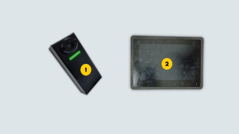
Figure 2 - Primary Components
| 1 | Audit HD Camera |
| 2 | 10.1-in Touch Screen Display |
1.3 Cables:
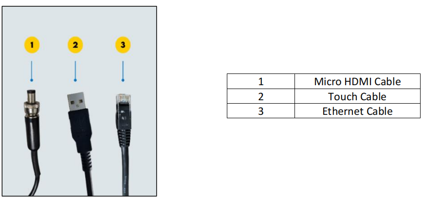
Figure 3 - Cables
Assembly - Hardware Installation:-
2.1 Pre-requisite for installation:
The vAudit pole is either drilled to a table using a bracket or clamped at the side. Ensure the table meets the specifications given below.
| Specifications | Table Clamp Version | Table Bracket Version |
Table Material | Wood (or) Metal | NA |
| Table Thickness | Up to 2 in / 5 cm | Up to 1 in / 2 cm |
| Table Space at the Bottom | 2 in / 5 cm | NA |
2.2 Pole Assembly:
Step 1: Take the lower pole. Clamp it to a table.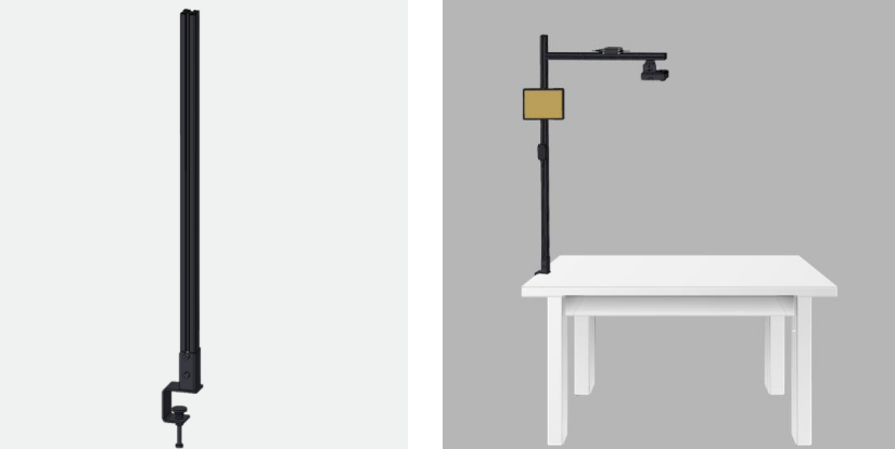
Figure 4 - Lower pole clamping to table
Step 2: Slide the arm pole to the lower pole. Tighten the T-Nut on the pole with arm using 4 mm Allen
Key.
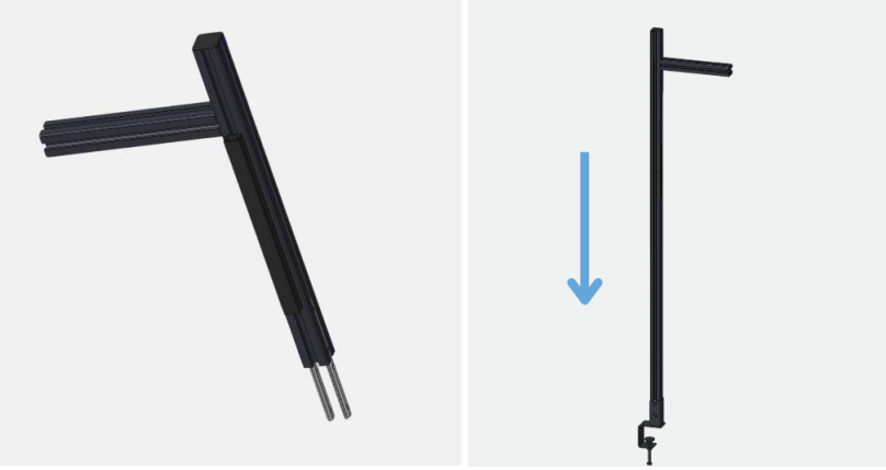
Figure 5 - Pole with Arm Placement
Step 3: Slide the pole extension to the horizontal arm pole. Tighten the pole extension with 4 mm Allen Key.
 Figure 6 - Pole Extension
Step 4: Slide the Audit HD camera into the pole. Tighten the Audit HD camera using 4 mm Allen Key.
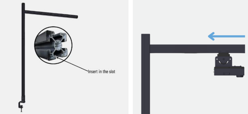
Figure 7 - Audit HD Camera Installation
Step 5: Place the AHD camera power adapter on the upper pole as shown
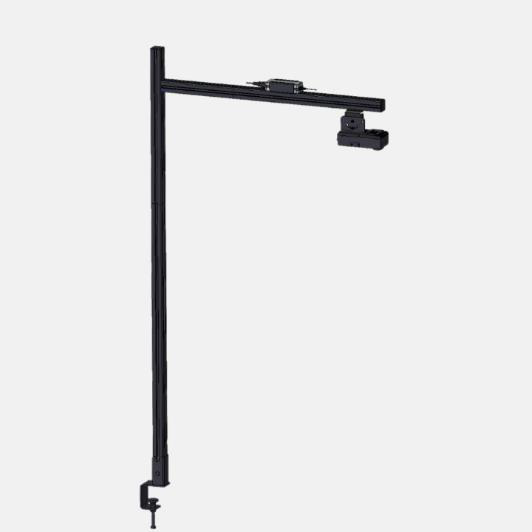
Figure 8 - AHD Power Adapter Placement
Step 7: Fix the power adapter for display to the pole using the 4 mm Allen Key
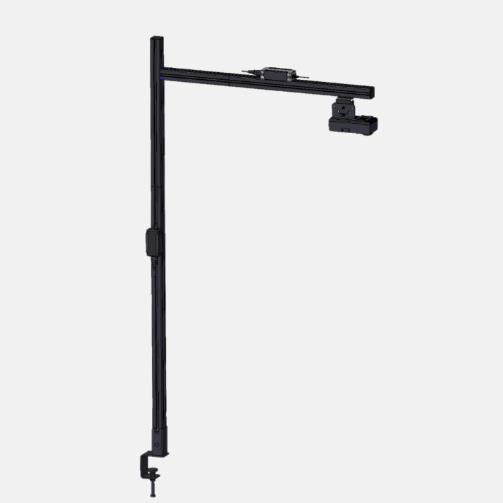
Figure 9 - Power Adapter Placement for Display
Step 8: Fix the display clamp. Then place the display using that clamp.

Figure 10 - Display Placement
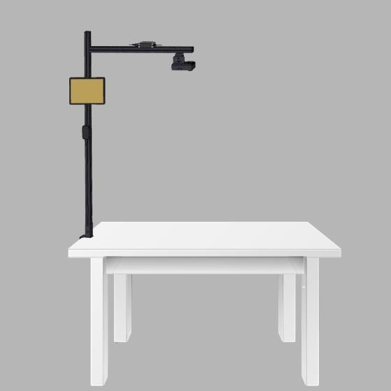
Figure 11 - The completed setup of vAudit (Full Setup View)
2.3 Wire Connections:-
2.3.1 Display Connections:
The wire connections for the Touchscreen display are outlined below.

Figure 12 - Display Connection Ports
 Figure 13 - Wires to the display
2.3.2 Audit HD Camera Connections:
The wire connections for the Audit HD camera are outlined below.
 Figure 14 - Audit HD Camera Wire Connections (Back View)
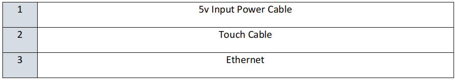
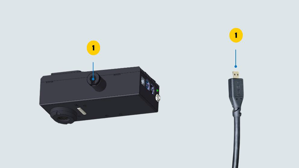
Figure 15 - vAudit Wire Connections (Side View)
2.4 Voltage Check:-
Ensure the power supply is within the specified voltage limits as given below. Check the voltage between different ports before switching on the device.

Figure 16 - Plug Point (USA)
| AC Power Voltage Range in the USA | ||
| Neutral to Hot | Hot to Earth | Neutral to Earth |
| 110V to 120V | 110V to 120V | 0 to 3V |
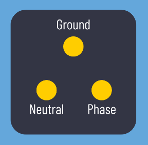
Figure 17 - Plug Point (India) AC Power Voltage Range in India
| AC Power Voltage Range in India | ||
Phase to Neutral | Phase to Earth | Neutral to Earth |
| 220 to 240VAC | 220 to 240VAC | 0 to 3VAC |
Once the voltage is within the specified range. Plug the AHD and display power cable to the main power socket.
Network Configuration:-
vAudit works with a default IP in DHCP mode. However, network configuration is required when Static IP is the preferred mode of connection. Click here for KB Article on how to configure the network.
If you need any support , please drop a mail to vmeasure@visailabs.com or Click here to Submit a Ticket.
Was this article helpful?
That’s Great!
Thank you for your feedback
Sorry! We couldn't be helpful
Thank you for your feedback
Feedback sent
We appreciate your effort and will try to fix the article