Unboxing:-
1.1 Pole Components:
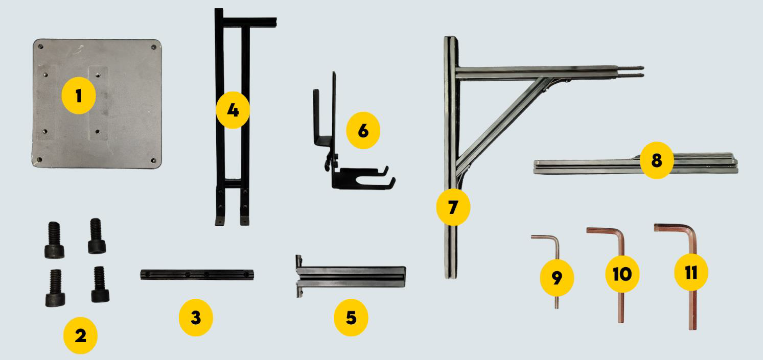
Figure 1 - Pole Components
| 1 | Base Plate |
| 2 | M10 x 20 bolts (4 nos) |
| 3 | T-Nut (4 nos – Inside the mechanicals) |
| 4 | Base Pole |
| 5 | Orientation Rod (Optional) |
| 6 | Accessory Clamp |
| 7 | Upper Pole With Arm |
| 8 | 530 mm Pole |
| 9 | 4 mm Allen Key |
| 10 | 6 mm Allen Key |
| 11 | 8 mm Allen Key |
1.2 Primary Components:
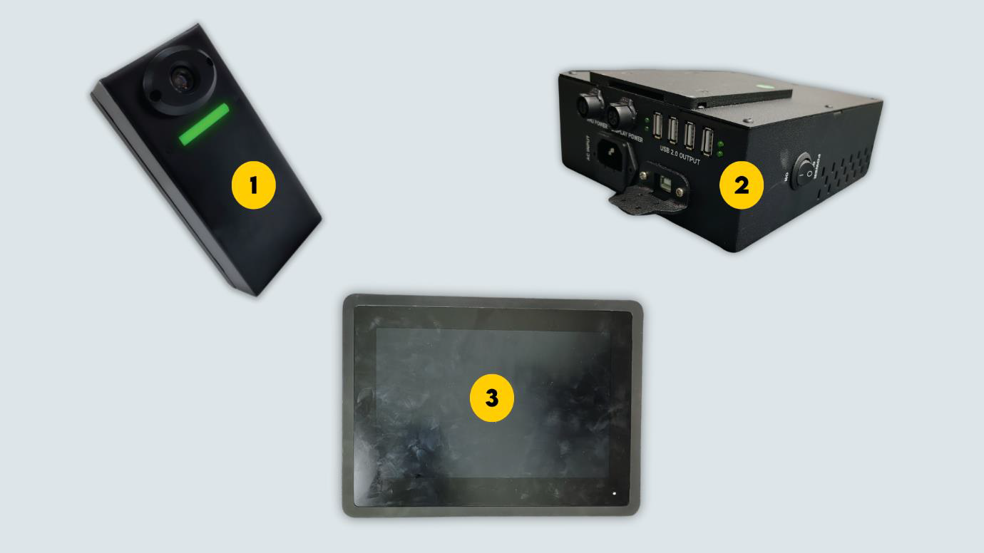
Figure 2 - Primary Components
| 1 | Automated Barcode Scanner |
| 2 | Power Hub Unit |
| 3 | 10.1-in Touch Screen Display |
1.3 Additional Components:
| 1 | Zebra Barcode Scanner |
| 2 | Weighing Scale |
| 3 | Weighing Scale Display |
Assembly - Hardware Installation:-
2.1 Pole Assembly:
Step 1: Place the base plate on a flat and steady surface
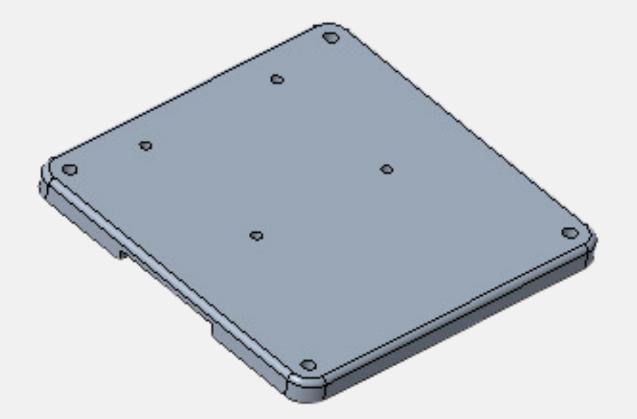
Figure 3 - Base Plate
Step 2: Take the lower pole place it on the baseplate as shown. The arm should be pointing outwards from the baseplate.
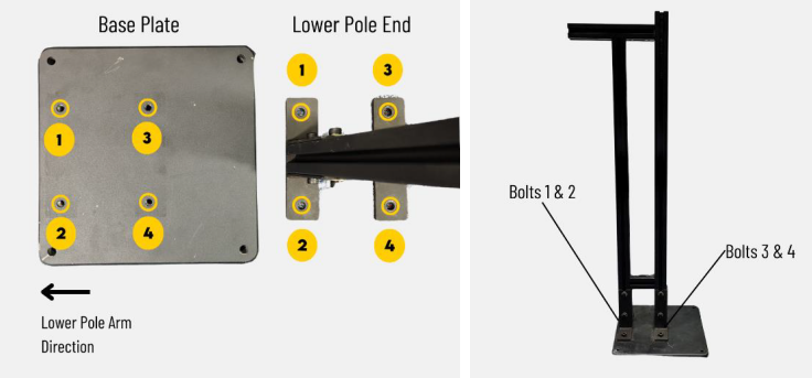
Figure 4 - Lower Pole Placement
Step 3: Use the M10 x 20 nuts (4 nos) and 8 mm Allen key to fit the lower pole.
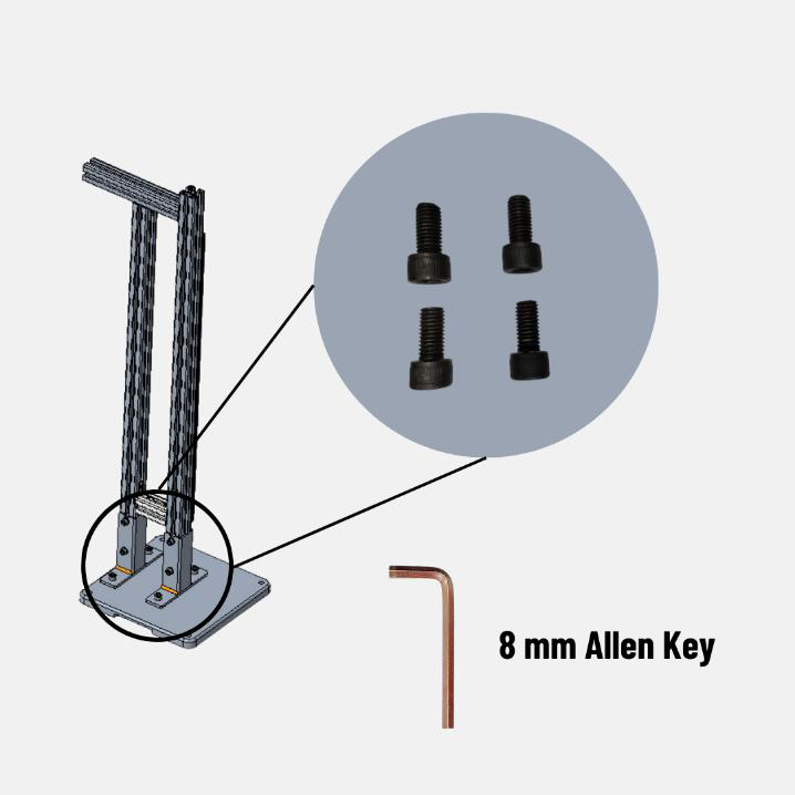
Figure 5 - Securing the lower pole
Step 4: Use the 4 mm Allen Key to loosen the screws of the T-nut (4 nos) and pull it up, Ensure it is extended halfway. Then tighten the bottom screws on both sides.
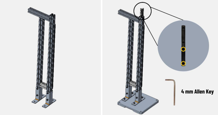
Figure 6 - Lower Pole T-Nut
Step 5: Slide the upper pole with arm into the T-Nut. Refer Figure 4 for correct placement.

Figure 7 - Upper Pole With Arm Insertion
Checkpoint 1: Refer V1 marking on the lower and middle pole.
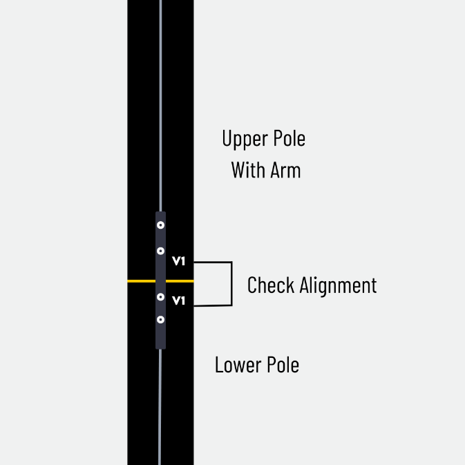
Figure 8 - V1 Marking
Step 6: Tighten the two screws on the top half of the T-Nut using 4 mm Allen Key on both sides.
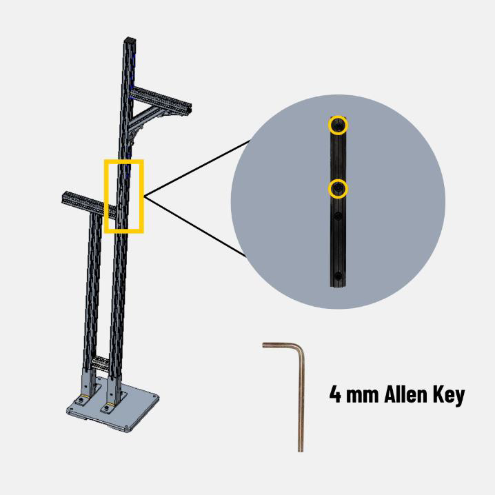
Figure 9 - Fixing the Upper With Arm
Step 7: Use the 4 mm Allen Key to loosen the four screws of the T-nut (2 nos) and pull it up. Ensure it is extended halfway. Then tighten the bottom screws on both sides.
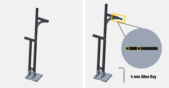
Figure 10 - Upper Pole With Arm T-Nut Position
Step 8: Slide the 530 mm pole into the upper pole with arm.
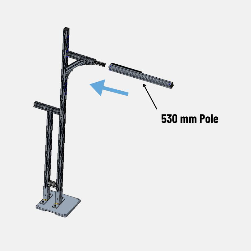
Figure 11 - Extension Pole Insertion
Checkpoint 2: Refer H2 marking on the upper and extension pole.
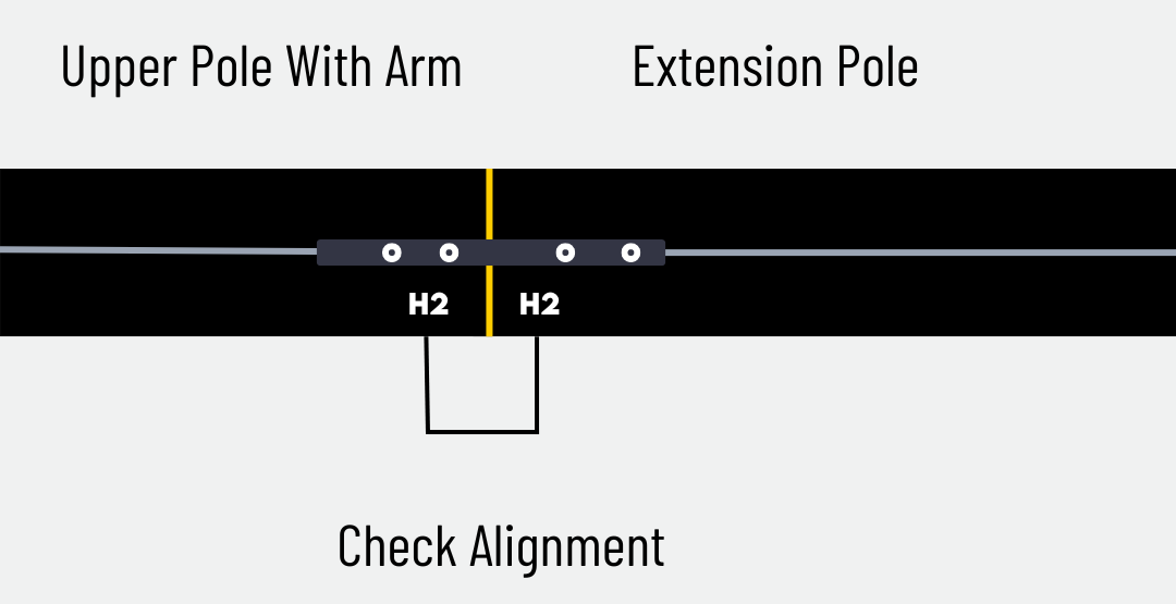
Figure 12 - H2 Alignment
Step 9: Tighten the two screws on the top half of the T-Nut using 4 mm Allen Key on both sides.
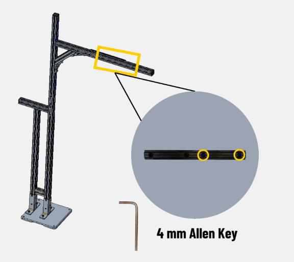
Figure 13 - Fixing of 530 mm Pole
2.2 Automatic Barcode Scanner & VHU Installation:
Step 1: Slide the Automatic Barcode Scanner into the extension pole (H3). Slide it for 2 or 3 inches and tighten the two screws of the Automated Barcode Scanner camera clamp.
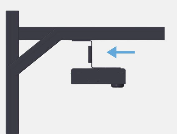
Figure 14 - Barcode Scanner Insertion
Step 2: Insert Vision Head Unit and tighten the screws on both ends with 4 mm Allen Key.
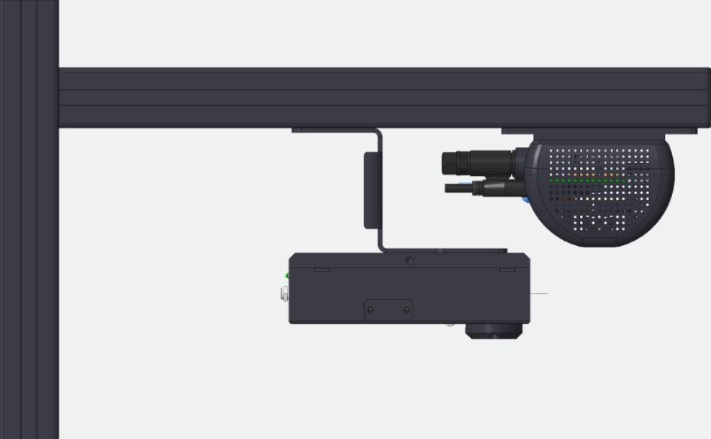
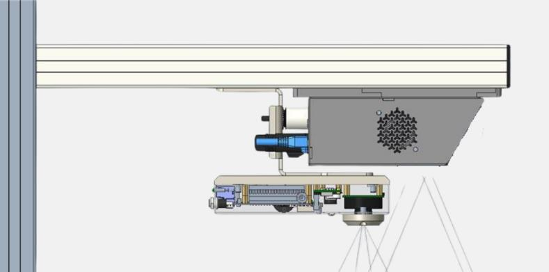
Figure 15 - VHU & Barcode Scanner Position (VHU Version V1 & V2)
Note: Ensure the automated barcode scanner does not block the Vision Head Unit’s view.
2.3 Accessories Installation With Orientation Rod:
Orientation Rod is an optional mechanical provided to install the display in the direction of
the VHU. Skip to Section 2.3, if not applicable.
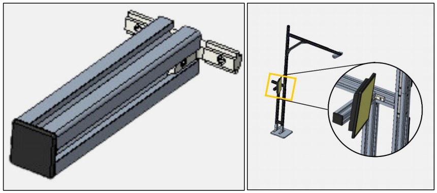
Figure 16 - Orientation Rod
Step 1: Slide the orientation rod into the arm of the lower pole.
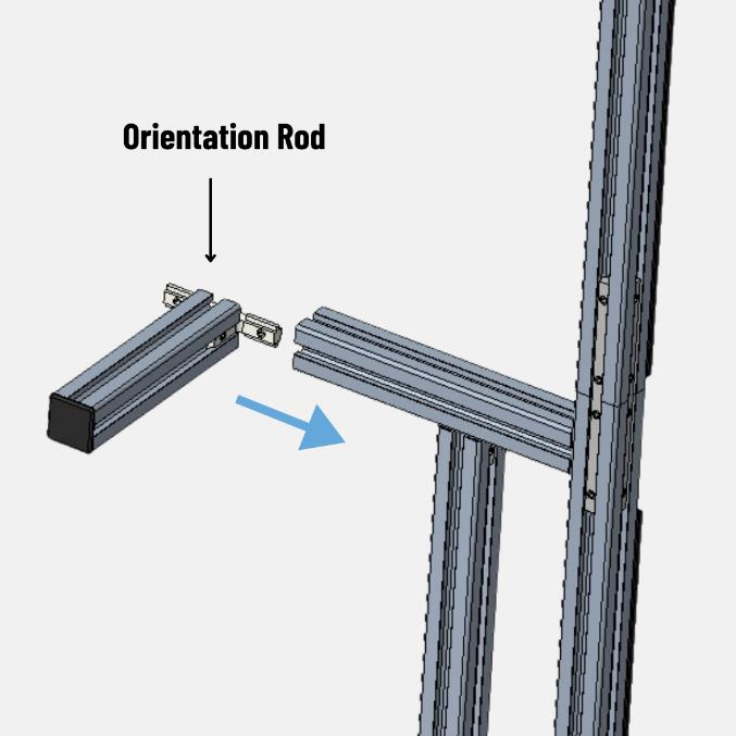
Figure 17 - Orientation Rod Placement
Step 2: Tighten the screws using 4 mm Allen Key.
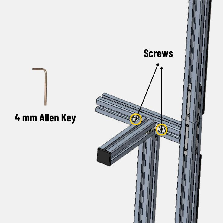
Figure 18 - Fixing of Orientation Rod
Step 3: Slide the accessory clamp in the orientation rod.
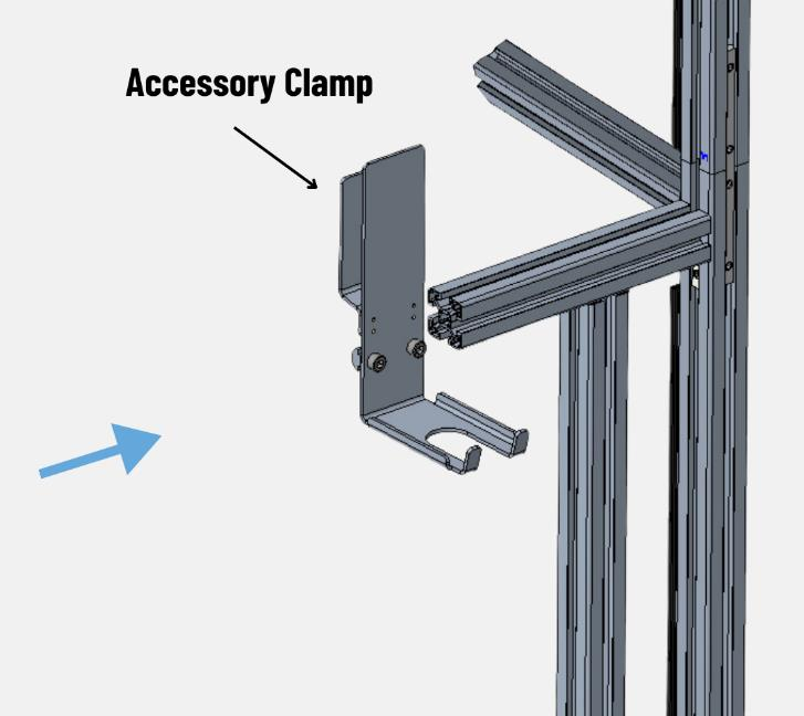
Figure 19 – Accessory Clamp Insertion
Step 4: Use the 6mm Allen Key to fix the accessory clamp.
Figure 20 – Fixing of Accessories Clamp
2.4 Accessories Clamp Installation Without Orientation Rod
Step 1: Slide the accessory clamp in the arm of the lower pole.
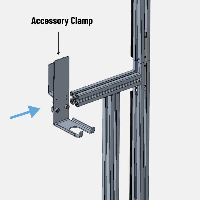
Figure 21 – Accessories Clamp Insertion
Step 2: Use the 6mm Allen Key to fix the accessory clamp.
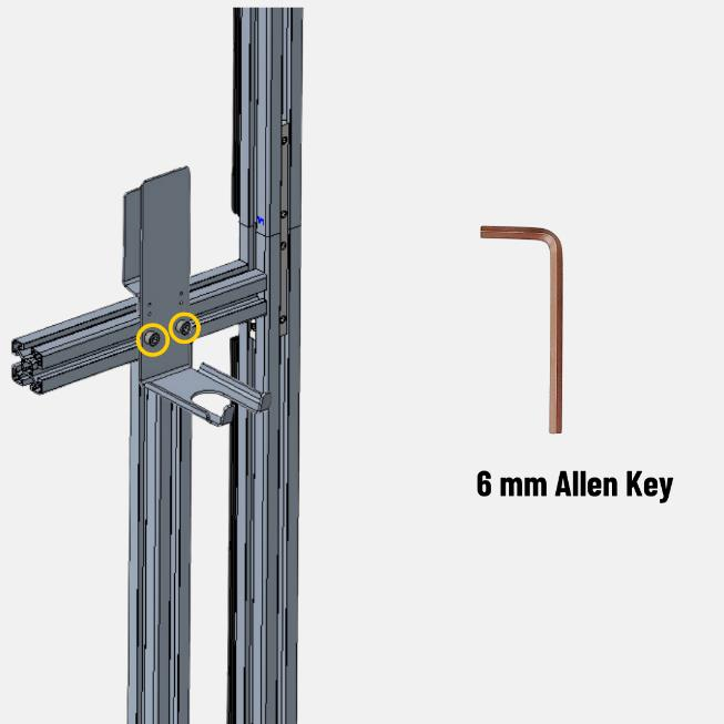
Figure 22 – Fixing of Accessories Clamp
2.5 Wire Connections:-
2.5.1 Display Connections:
The wire connections for the Touchscreen display are outlined below.

Figure 23.1 – Display Connection Ports
 Figure 23.2 – Wires to the display
Slide the display into the accessory clamp after wire connections.
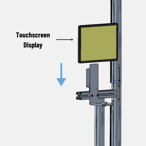
Figure 24 – Fixing the Display
2.5.2 Power Hub Connections:
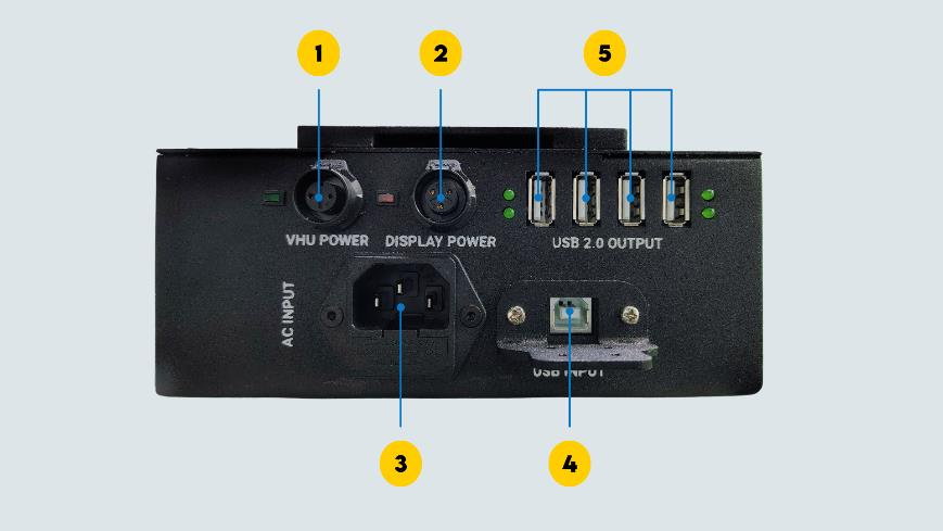
Figure 25.1 – Power Hub Unit Ports

Figure 25.2 – Wires to the Power Hub Unit
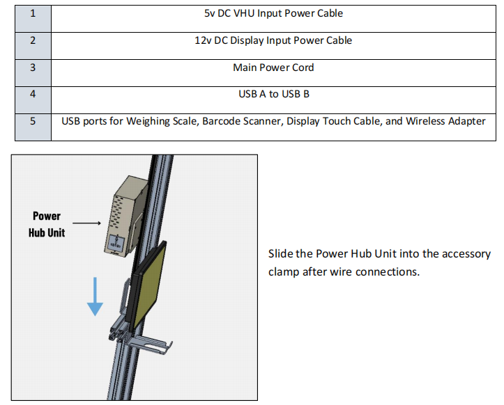
Figure 26 – Power Hub Unit Placement
2.5.3 Vision Head Unit Connections:
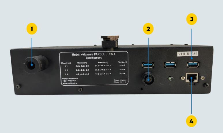
Figure 27.1 –Vision Head Unit Ports
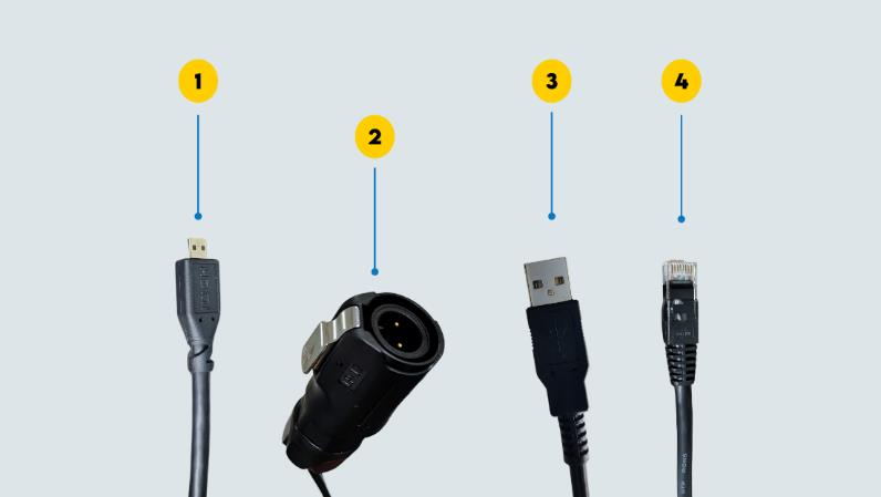
Figure 27.2 – Wires to the Vision Head Unit

2.5.4 Automated Barcode Scanner Wire Connections:
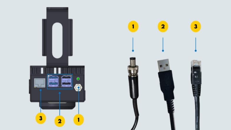
Figure 28 - ABS Wire Connections (Back View)

2.6 Voltage Check:-
Ensure the power supply is within the specified voltage limits as given below. Check the voltage between different ports before switching on the device.

Figure 29 - Plug Point (USA)
| AC Power Voltage Range in the USA | ||
| Neutral to Hot | Hot to Earth | Neutral to Earth |
| 110V to 120V | 110V to 120V | 0 to 3V |

Figure 30 - Plug Point (India) AC Power Voltage Range in India
| AC Power Voltage Range in India | ||
Phase to Neutral | Phase to Earth | Neutral to Earth |
| 220 to 240VAC | 220 to 240VAC | 0 to 3VAC |
Once the voltage is within the specified range. Plug the AHD and display power cable to the main power socket.
Network Configuration:-
Automatic Barcode Scanner works with a default IP in DHCP mode. However, network configuration is required when Static IP is the preferred mode of connection. Click here for KB Article on how to configure the network.
If you need any support , please drop a mail to vmeasure@visailabs.com or Click here to Submit a Ticket.
Was this article helpful?
That’s Great!
Thank you for your feedback
Sorry! We couldn't be helpful
Thank you for your feedback
Feedback sent
We appreciate your effort and will try to fix the article