Top Willing and Waveshare Display to Faytech Display - ROW Conversion Process Document
Components:
1. Cable Assembly 2.1mm ID, 5.5mm OD Plug, Thread Lock with Linko 3–Pin Connector.
2. USB Type A to USB Type B (300mm).
3. Faytech 10.1 Inch Display
Assembly procedure:
Step 1: Before dismantling the display, ensure the device is turned OFF. Refer to Figure 1 for the Top willing display and Figure 2 for the Waveshare display.
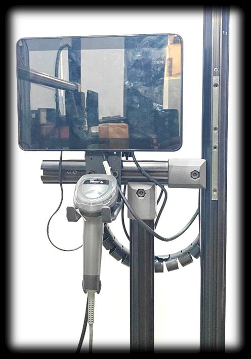
Figure 1
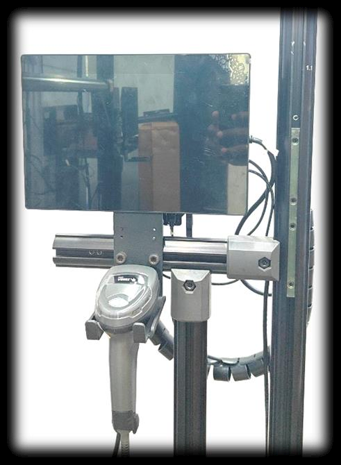
Figure 2
Step 2: Remove the Barcode from the DBU clamp as shown in Figure 3 & 4
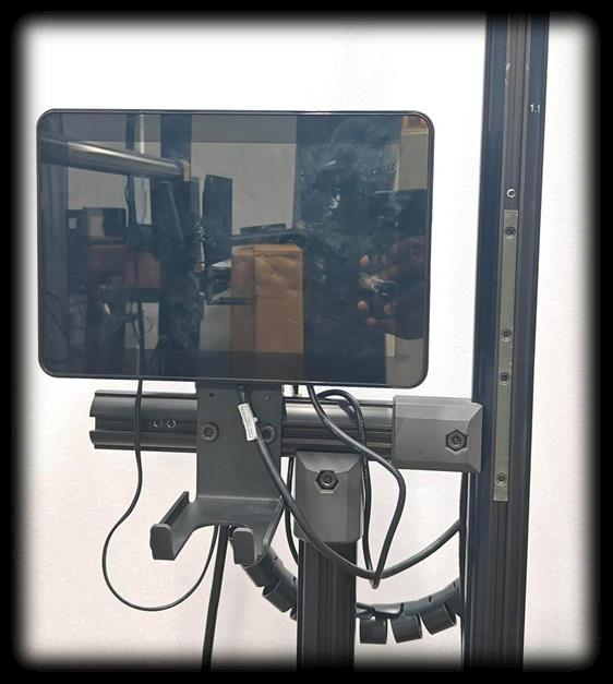
Figure 3
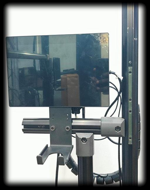
Figure 4
Step 3: Take the Display from the DBU clamp and disconnect the display input cables from the displays as shown in Figures 5 and 6.
 Figure 5
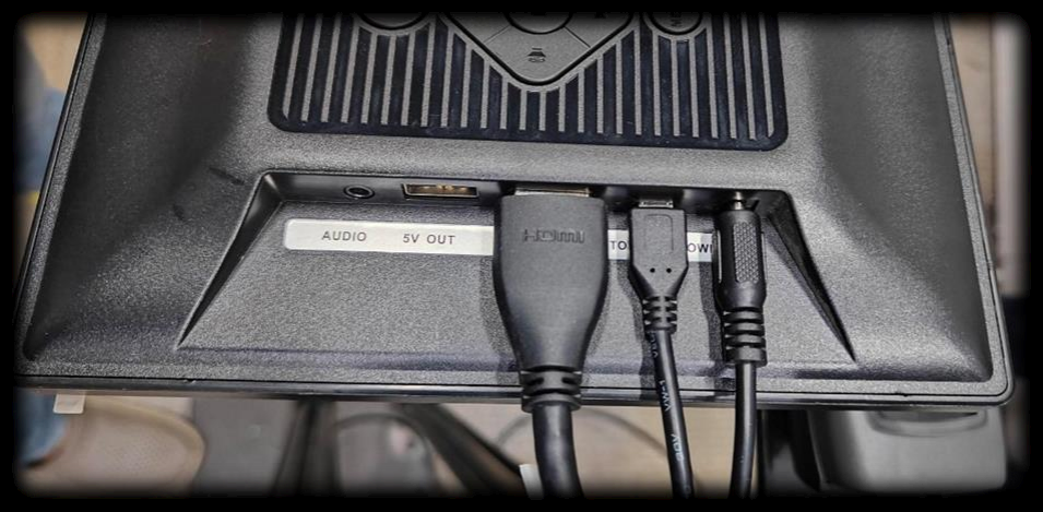
Figure 6
Step 4: After removing the Cables from the displays as shown in Figures 7 & 8
 Figure 7
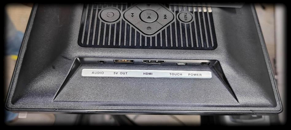
Figure 8
Step 5: Take the PHU from the DBU clamp and remove the existing Linko 3-Pin Power input cable and touch cable from the PHU as shown in Figure 9.
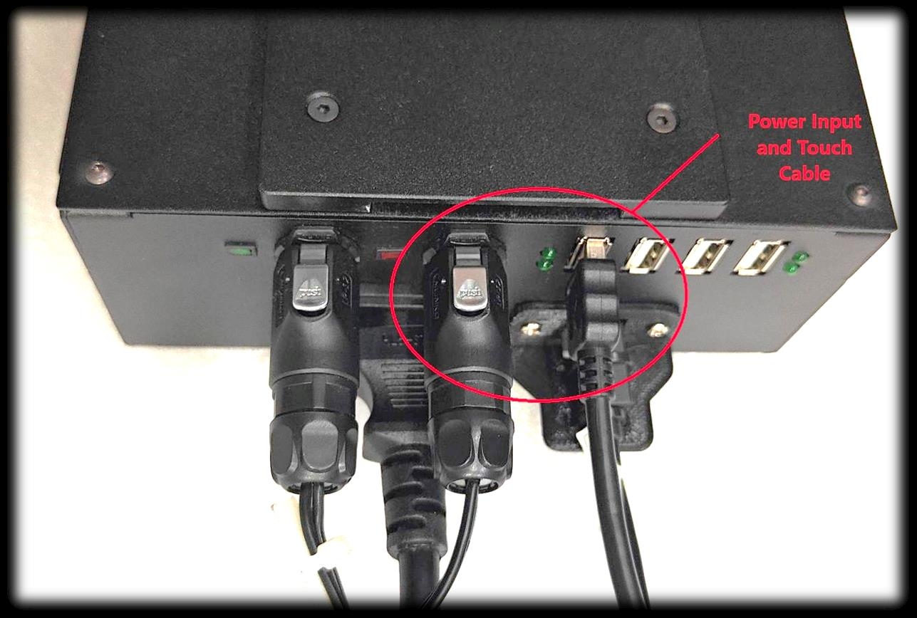
Figure 9
Step 6: After removing the cables from the PHU as shown in Figure 10.
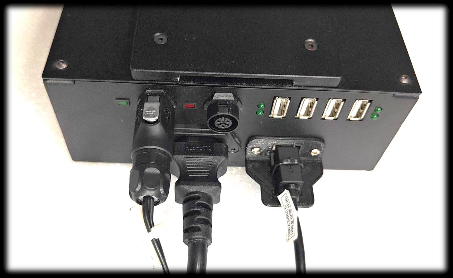
Figure 10
Step 7: Connect the Cable Assembly 2.1mm X 5.5mm Plug, Thread Lock with Linko 3–Pin Connector into the PHU as shown in Figures 11&12.
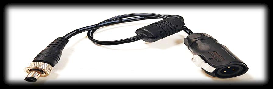
Figure 11
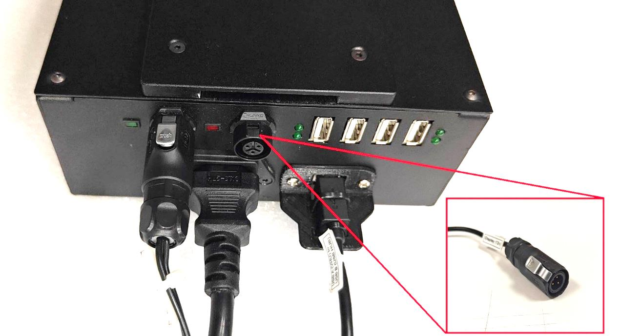
Figure 12
Step 8: Connect the Touch cable USB Type-A port into the PHU USB HUB as shown in Figure 13.
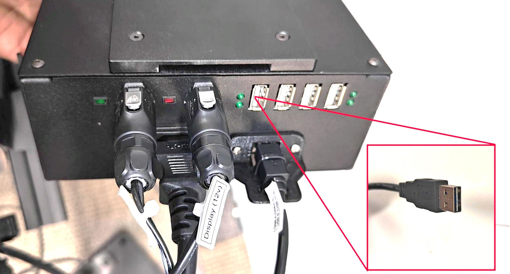
Figure 13
Step 9: Take the Faytech Display with display holder and ensure that the display holder slider slot is at the port side, as shown in Figure 14. 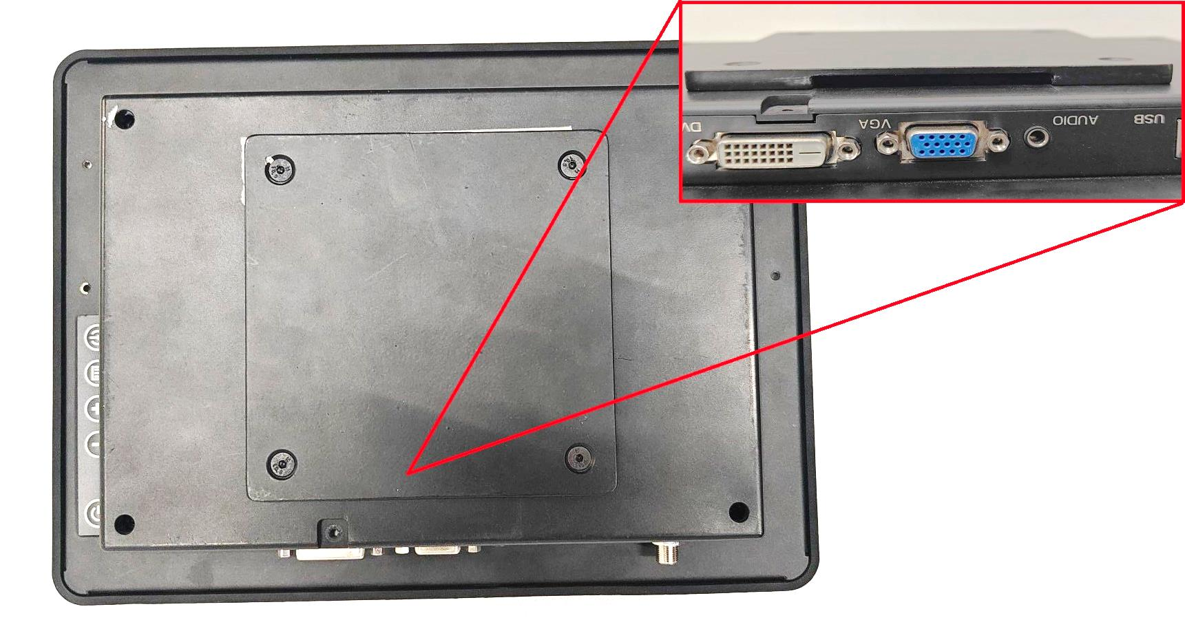
Figure 14
Step 10: Connect the Display Power Input, HDMI Cable and USB Type B Touch Cable into the Display as shown in Figure 15.
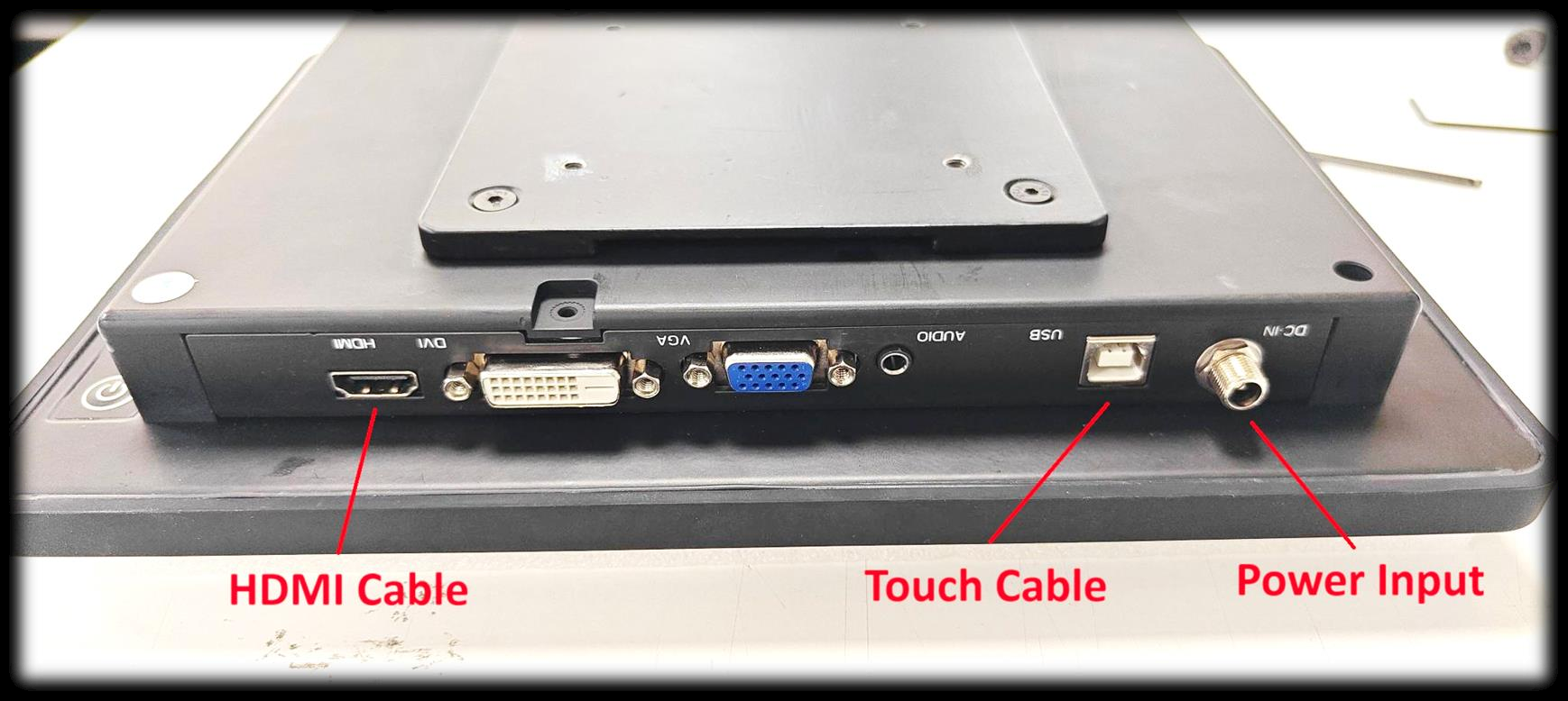
Figure 15
Step 11: Connect the USB Type A to Type B touch cable into the Display as shown in Figure 16.
 Figure 16
Step 12: Connect the Display power input cable to the display and rotate the thread in clockwise to lock as shown in Figure 17.
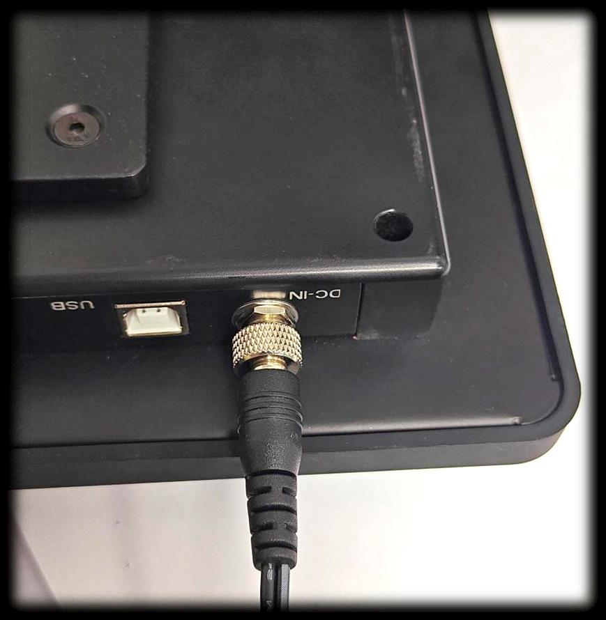
Figure 17
Step 13: Connect the HDMI Cable into the Display as shown in Figure 18.
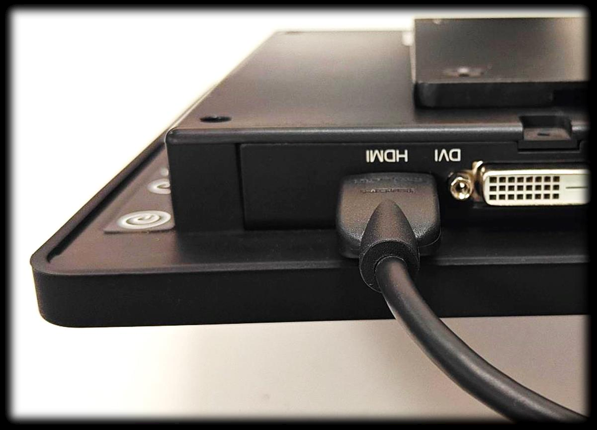
Figure 18
Step 14: Connect the weighing scale, and Barcode Cable into USB Hub as shown in Figure 19.
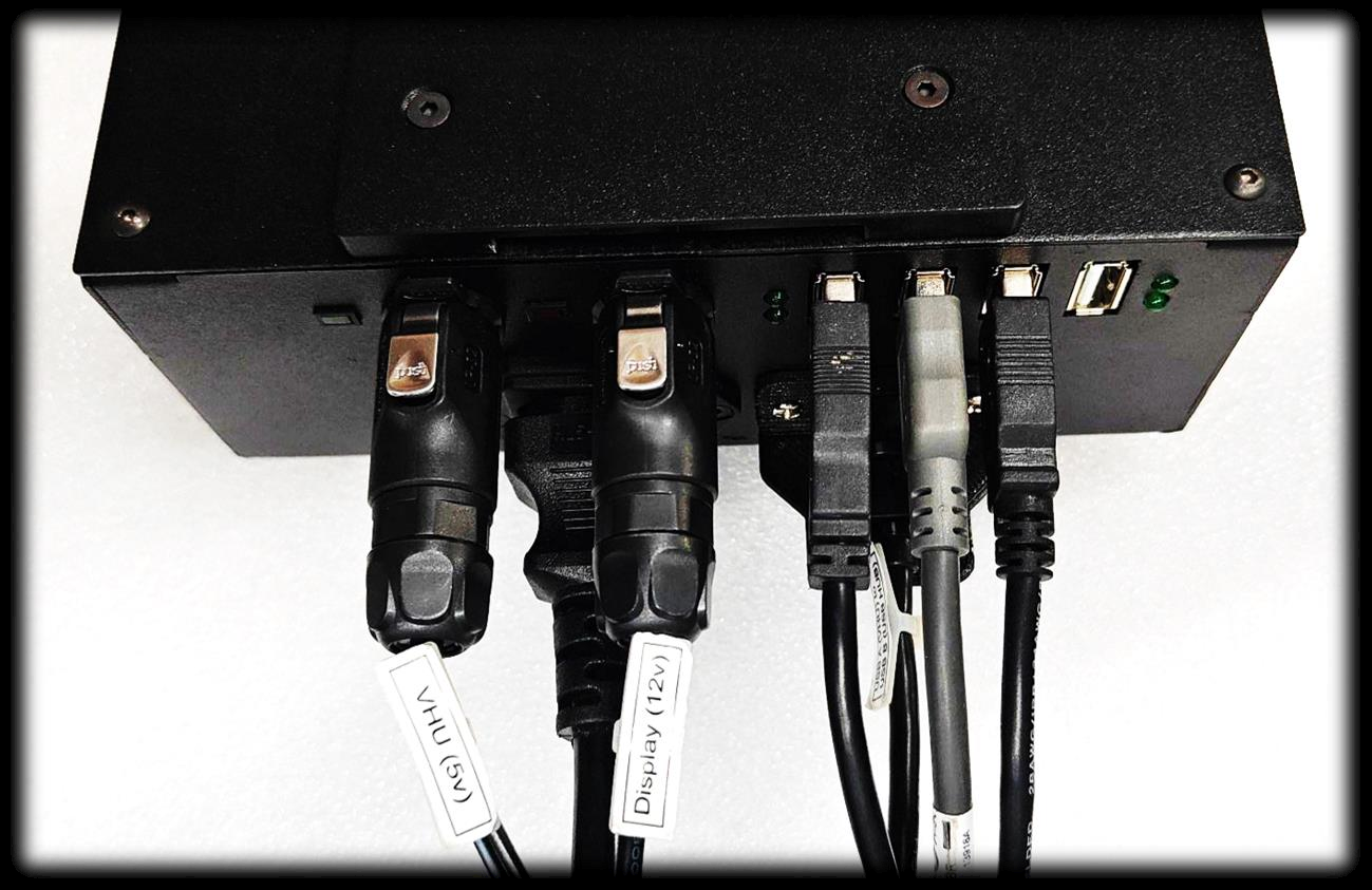
Figure 19
Step 15: Slide the PHU and display into the DBU clamp as shown in Figure 20.
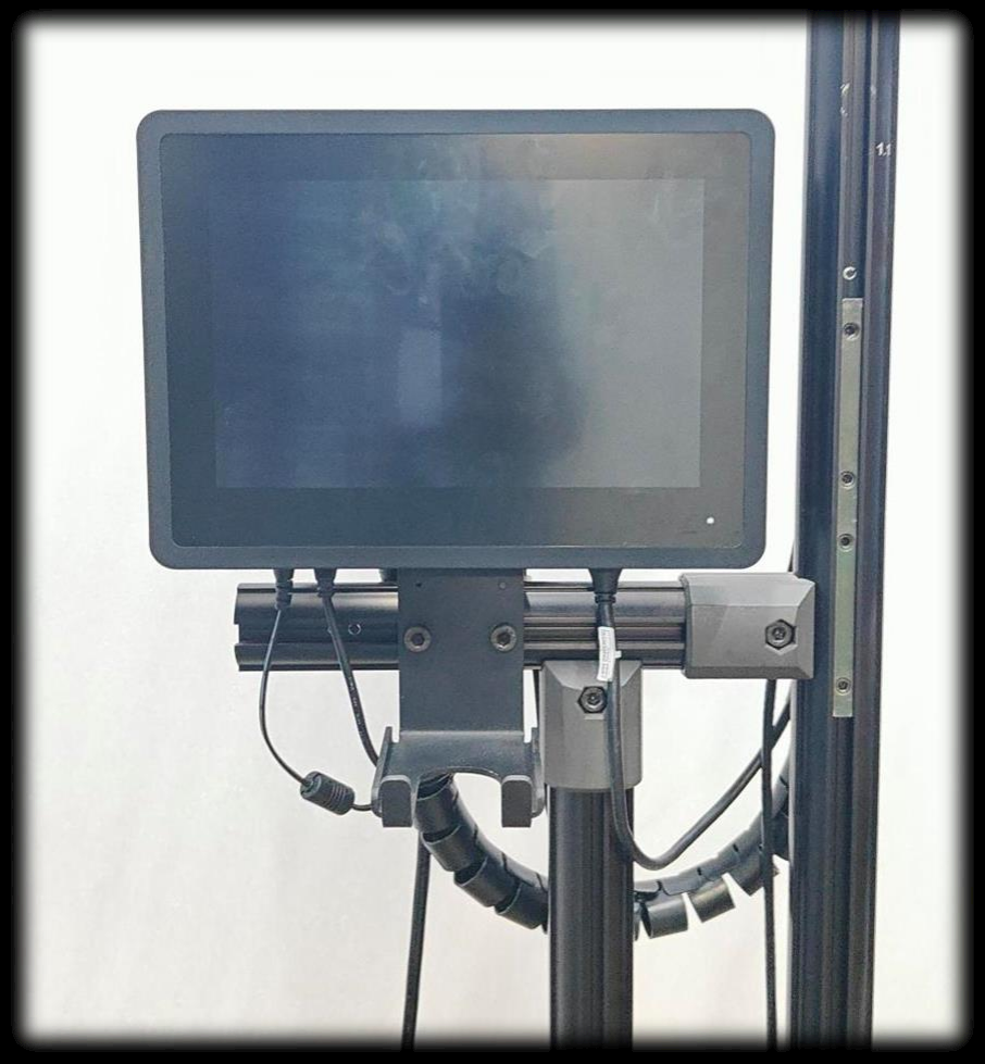
Figure 20
Step 16: Place the barcode in Barcode clamp and Power ON the setup, as shown in Figure 21.
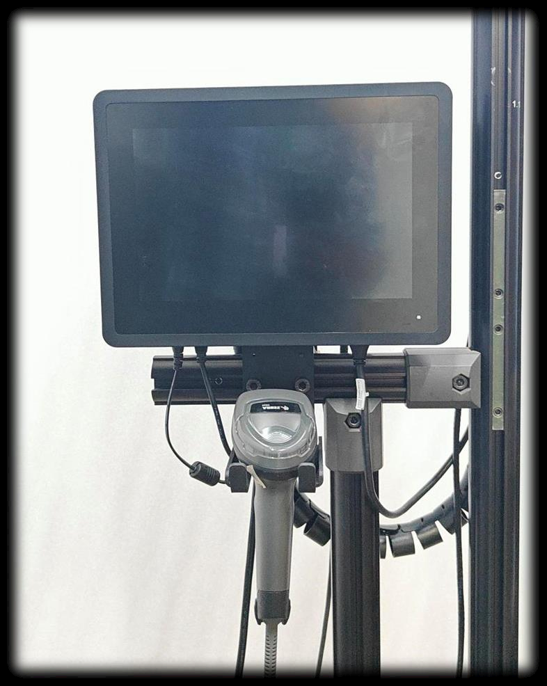
Figure 21
Please find the attached document for reference.
If you need any support , please drop a mail to vmeasure@visailabs.com or Click here to Submit a Ticket.
Was this article helpful?
That’s Great!
Thank you for your feedback
Sorry! We couldn't be helpful
Thank you for your feedback
Feedback sent
We appreciate your effort and will try to fix the article